Published 03/31/2025


In our September 2024 blog post, I summarized Addendum n to ASHRAE Standard 90.1-2022, the Energy Standard for Sites and Buildings Except Low-Rise Residential Buildings. Addendum n enables design teams using the Indoor Air Quality Procedure (IAQP) with gas-phase air cleaning to reduce ventilation loads below levels required for designs using the Ventilation Rate Procedure (VRP).
When comparing designs using the IAQP and the VRP, the VRP design usually includes energy recovery. This is because VRP designs require large volumes of outdoor air, which triggers the need for ventilation load reduction design strategies such as energy recovery.
In this blog post, I show how an IAQP design utilizing gas-phase air cleaning, in lieu of a VRP design with energy recovery, maximizes ventilation load reduction to save system costs and improve energy efficiency while complying with Standard 90.1-2022.
ASHRAE Standard 90.1 includes prescriptive and performance pathways. While energy recovery is often required under the prescriptive pathway, energy recovery may not be required under the performance pathway (the Appendix G Performance Rating method) depending on the climate zone, supply airflow, and percent outdoor air. Figure 1 illustrates common compliance pathways with notes on when energy recovery may be required.

As shown in the Proposed Design example in Figure 1, energy recovery is not included nor is it required as it does not fall under Section 6.4 Mandatory Provisions (pre-requisites for the performance path). Instead, in the Proposed Design example the IAQP with gas-phase air cleaning is used to optimize ventilation energy.
How do we know the proposed design is optimal? Let’s look at energy modeling results from an example building where we compare a VRP with energy recovery Baseline Design with an IAQP with gas-phase air cleaning Proposed Design.
The example building is a 40,000 ft2 office building with a maximum occupancy of 400 people, located in Boston. Parameters for the sample building along with outdoor air and return air design conditions are summarized in Table 1.
Table 1– Example Building – General Information
| Parameter | Building Total |
| Climate Zone | 5A |
| Outdoor Air Design Conditions
|
90.8°F DB (Summer)
73.3°F WB (Summer) 7.4°F DB (Winter) |
| Return Air Conditions | 72°F DB (Summer)
60°F WB (Summer) 65°F DB (Winter) |
| Supply Air Conditions | 55°F DB
54°F WB |
| Building Type | Office |
| Floor Area | 40,000 ft2 |
| Occupancy | 400 |
| Toilet Exhaust | 2,000 CFM |
| HVAC Operating Schedule | 7AM – 7PM, 7 days/week |
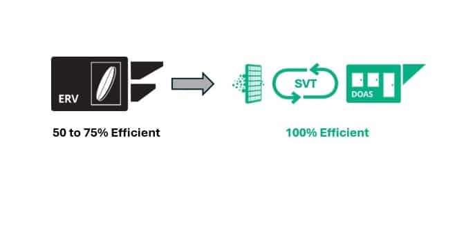
The outdoor air requirements for the Proposed Design were determined using the ASHRAE 62.1 IAQP calculator and an input of 2,000 CFM of clean air based on a 72% end-of-life formaldehyde efficiency for enVerid’s Sorbent Ventilation Technology® (SVT®). The IAQP outdoor air requirement is 2,000 CFM. The outdoor air is supplied by a dedicated outdoor air system (DOAS) without energy recovery, and the clean air is supplied by two enVerid HLR® 100M modules, which use SVT to remove harmful gaseous contaminants from indoor air, as shown in Figure 2.

Addendum n to ASHRAE Standard 90.1-2022 states that when designing systems in accordance with the IAQP, “baseline ventilation airflow rates in those zones are permitted to be greater than the proposed design and shall be calculated in accordance with Standard 62.1, Section 6.2, Ventilation Rate Procedure”.
Additionally, Section G3.2.2.9 of ASHRAE Standard 90.1-2022 requires the baseline building be modeled with 50% energy recovery if individual fan systems “have both a design supply air capacity of 5,000 CFM or greater and have a minimum design outdoor air supply of 70% or greater”.
As such, the outdoor air requirements for the baseline design were determined using the VRP. The VRP outdoor air requirement is 6,000 CFM. The outdoor air is supplied by a DOAS with 50% effective energy recovery, as shown in Figure 3.

The load benefits of the proposed design are shown in Table 2.
Table 2 – Proposed Design vs. Baseline Design – Load Reduction
| Parameter | Baseline Design | Proposed Design | Reduction | % Reduction |
| Outdoor Air Requirement | 6,000 CFM | 2,000 CFM | 4,000 CFM | 67% |
| Exhaust Air | 6,000 CFM | 2,000 CFM | 4,000 CFM | 67% |
| Clean Air Requirement | 0 CFM | 2,000 CFM | – | – |
| Peak Cooling Load | 20.2 tons | 10.7 tons | 9.5 tons | 47% |
| Peak Heating Load | 316 MBH | 168 MBH | 148 MBH | 47% |
| System Fan Power | 9.3 kW | 3.9 kW | 5.4 kW | 58% |
The energy benefits of the proposed design are shown in Table 3.
Table 3 – Proposed Design vs. Baseline Design – Energy Savings
| Parameter | Baseline Design | Proposed Design | Reduction | % Reduction |
| Cooling Energy | 21,265 kBtu | 7,088 kBtu | 14,177 kBtu | 67% |
| Heating Energy | 199,408 kBtu | 66,469 kBtu | 132,938 kBtu | 67% |
| Fan Energy | 138,968 kBtu | 58,192 kBtu | 80,500 kBtu | 58% |
| Total Energy | 359,371 kBtu | 131,756 kBtu | 227,615 kBtu | 63% |
| Total Energy | 9.0 EUI | 3.3 EUI | 5.7 EUI | 63% |
As shown in Table 2 and Table 3, the IAQP design with SVT delivers energy savings when compared to a baseline design that utilizes larger, more expensive ventilation systems with energy recovery. The reduction in energy is proven through ASHRAE 90.1 Appendix G compliant energy modeling and can help you more easily comply with energy codes and LEED requirements and earn custom utility incentives.
My colleagues and I have worked on countless IAQP designs that deliver similar results to those shown above in buildings that meet stringent energy codes. We would love to work with you to optimize your next HVAC design using the IAQP and SVT.

Director of Sales & Application Engineering, enVerid Systems
"*" indicates required fields

